Assembly instructions
Step 1: Prepare necessary tools
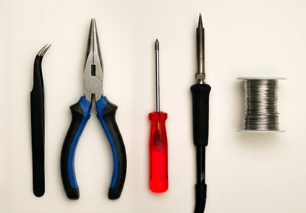
- A #1 Phillips head screwdriver
- Soldering iron
- Solder
- Optional: tweezers
- Needle-nose pliers
💡
Tip: A similar smallish Phillips head screwdriver could work.
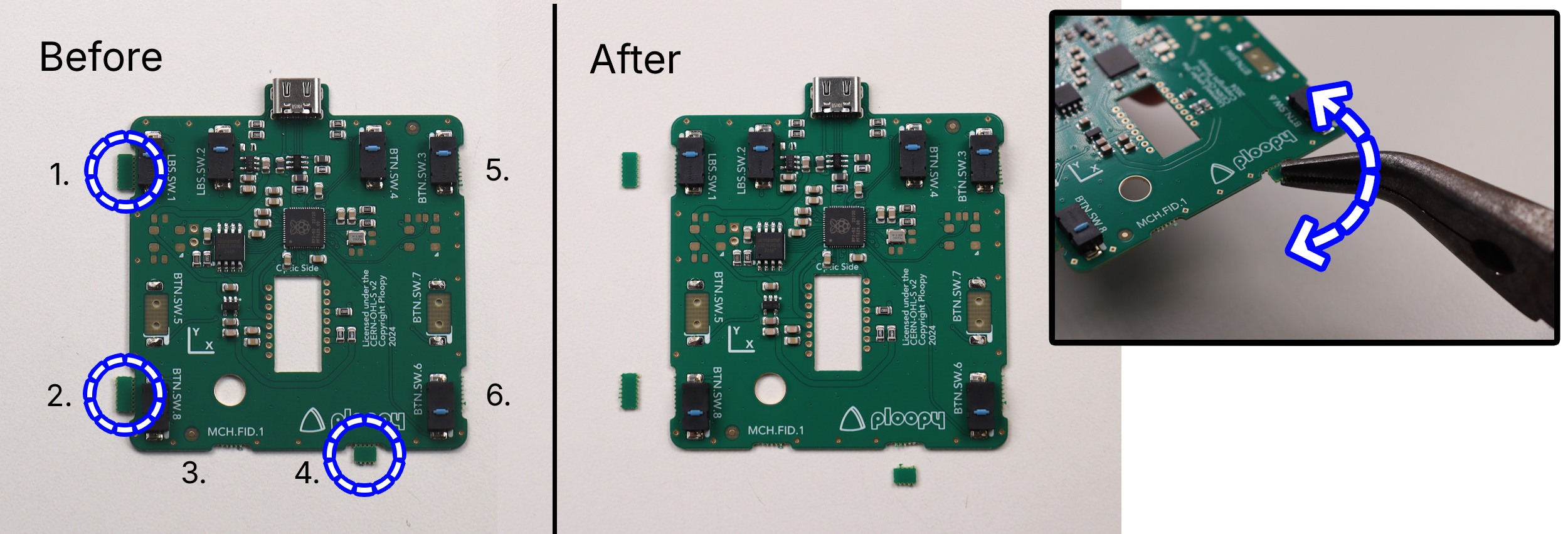
Step 2: Break off possible leftover tabs off the PCB
- There are up to six possible small tabs along the edge of the PCB as shown in the picture.
- Holding the PCB as pictured, gently break off any tabs using a pair of pliers.
🚨
Warning: These tabs should come off relatively easily, don’t use excessive force, it probably means you are doing it wrong!
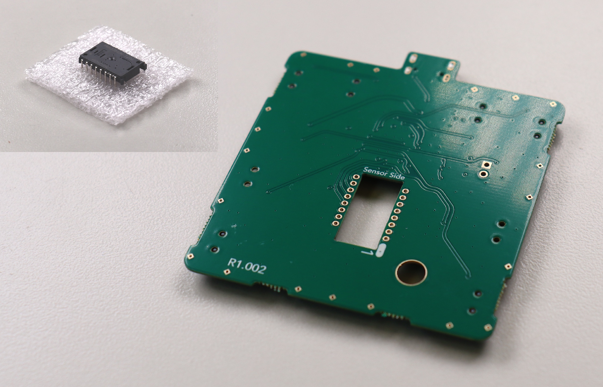
Step 3: Prepare parts for PCB soldering
Prepare the following components as pictured below:
- Printed circuit board
- PMW-3360 chip
💡
Tip: The PMW-3360 chip will come in a small piece of foam. Go ahead and remove it now.
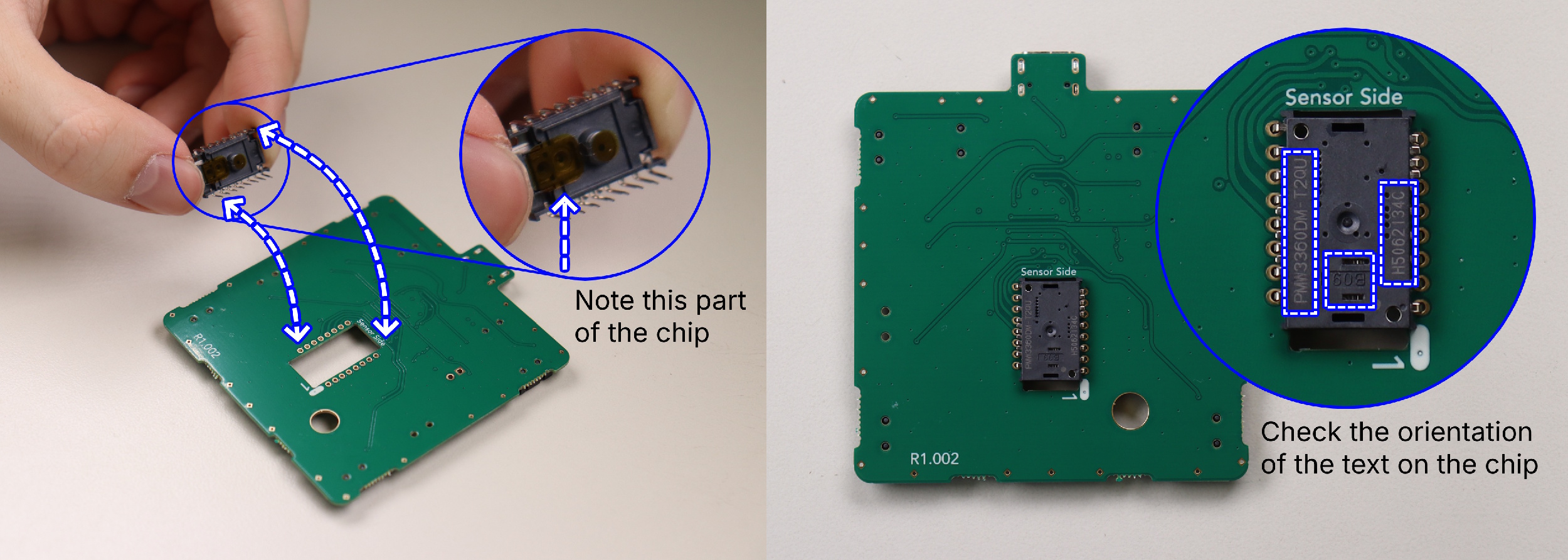
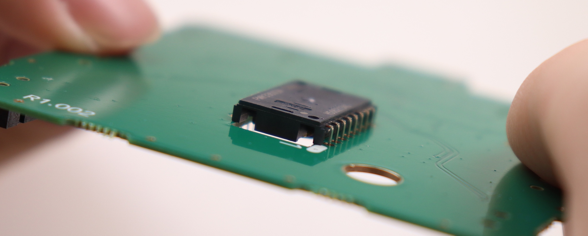
Step 4: Solder PMW-3360 sensor to printed circuit board
- Place the sensor onto the circuit board, ensuring the orientation is correct.
🚨
Warning: Use the cues presented in the following images to ensure the sensor is oriented correctly.
🚨
Warning: The sensor must be flat down as far as it can possibly slide into the holes before soldering.
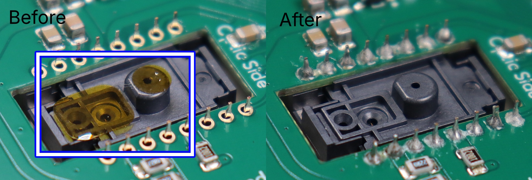
Step 5: Remove the tab of kapton tape on the PMW-3360 chip
💡
Tip: Try to do this step in a dust-free environment.
- There are two small tabs of orange tape covering the sensor's main holes. Remove them now.
ℹ️
Info: Check your solder joints during this step to ensure that they are good. To know if they are good, consult the
soldering FAQ.
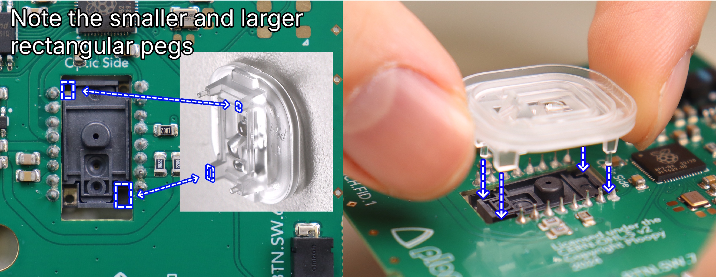
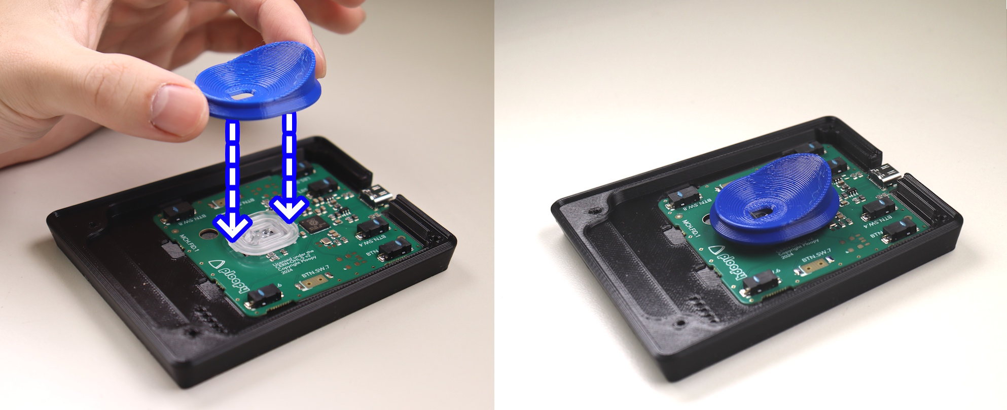
Step 6: Attach the PMW-3360 optic to the PMW-3360 chip
- Orient the optic as shown in the image before insertion.
🚨
Warning: It should NOT require any force to insert fully; if it does, remove it and check the orientation before trying again.
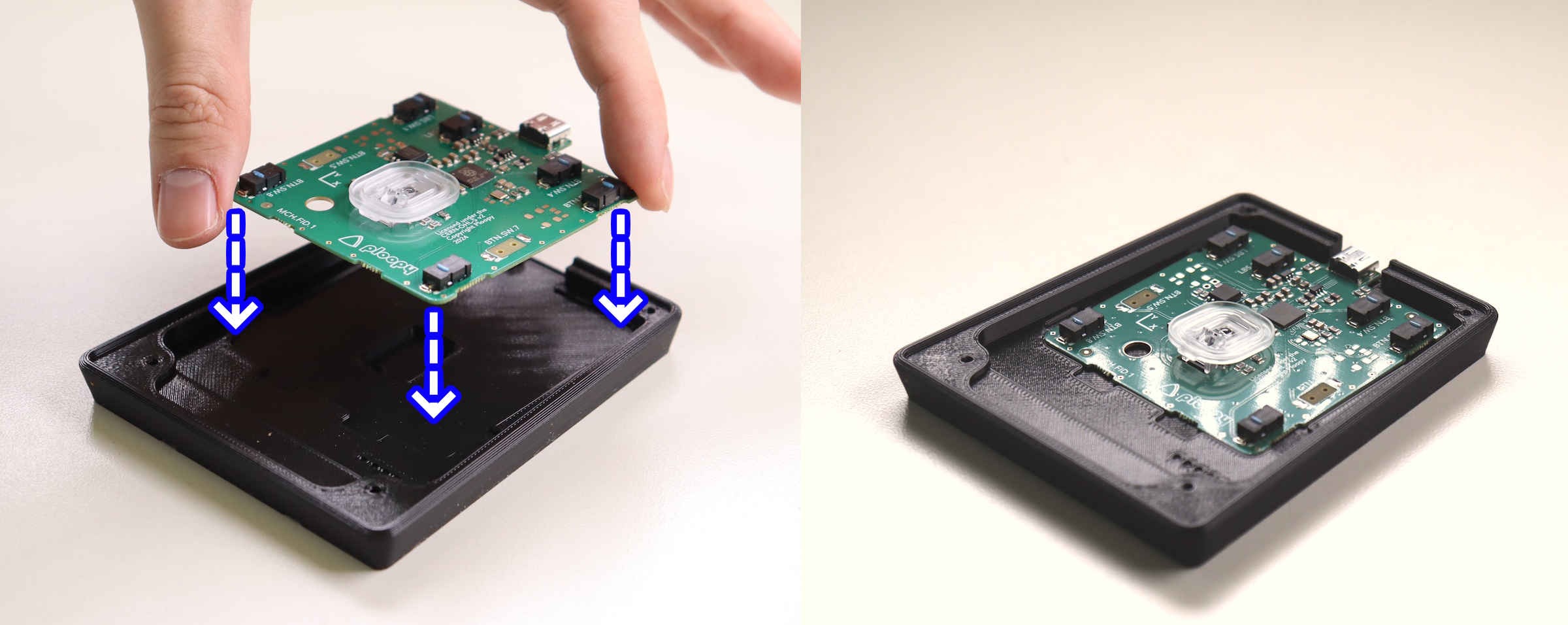
Step 7: Place the PCB into the Base
- This should be straightforward, the PCB should fit exactly as shown.
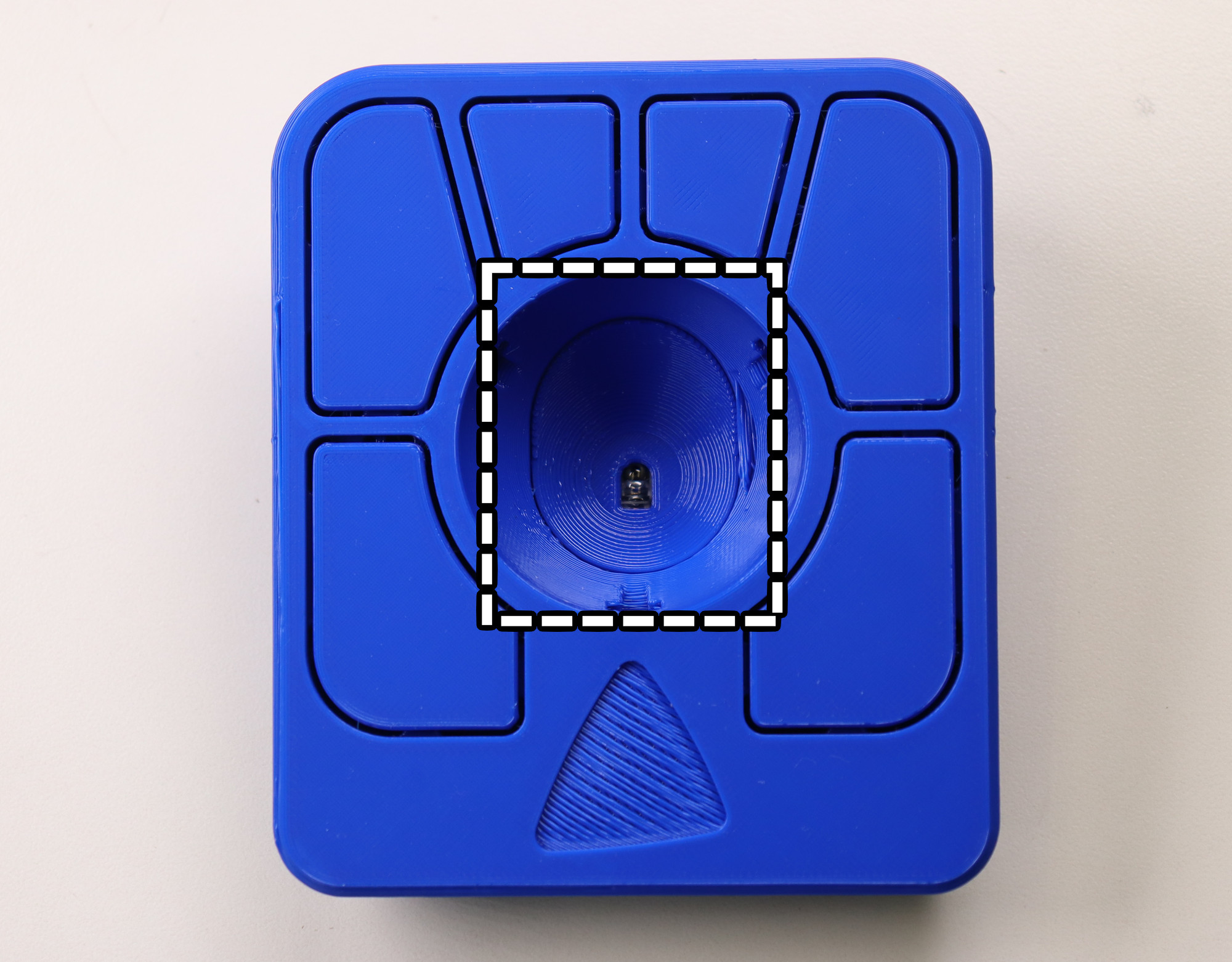
Step 8: Place the Sensor Cap on the PCB
- Place the sensor cap on the PCB as shown in the image.
💡
Tip: The Sensor Cap doesn't snap onto the PMW-3360 optic. It "floats" on top of the optic for now. Once fully assembled, the Sensor Cap will be securely held down.
Step 9: Place the Top Piece onto the Base Piece
- Place the top onto the base.
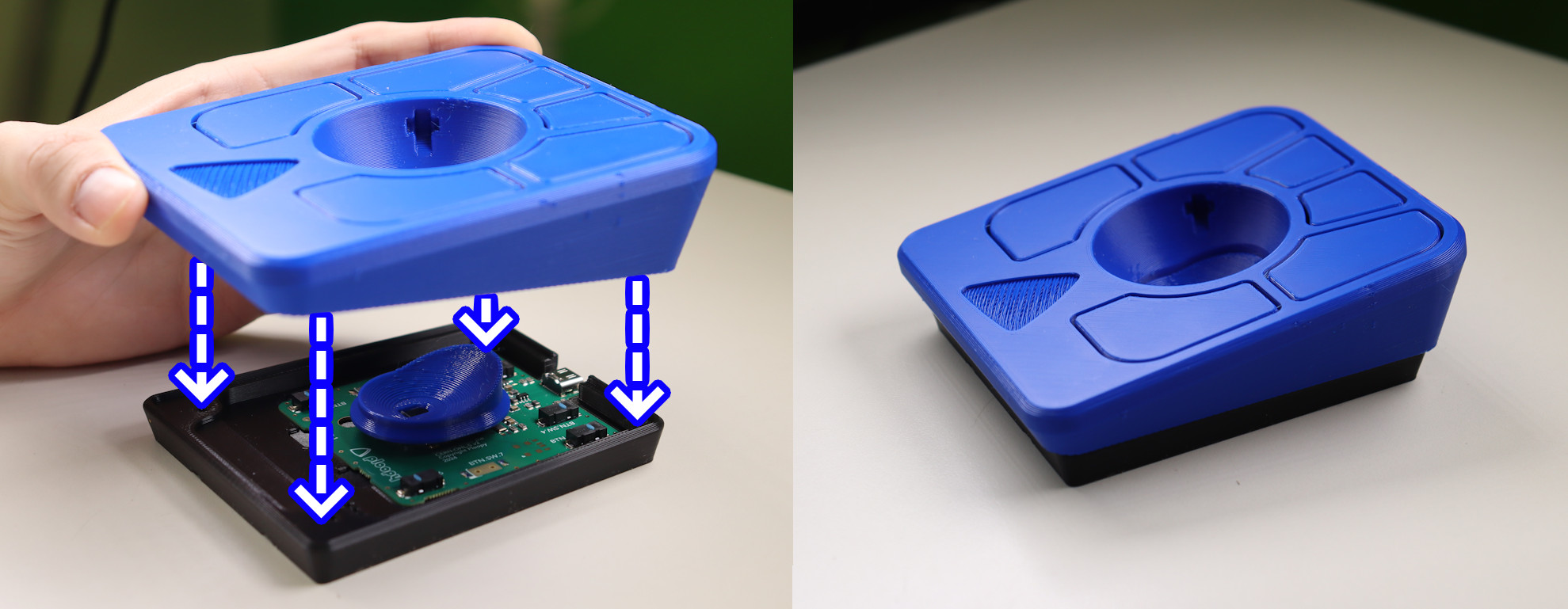
💡
Tip: If necessary, adjust the position of the Sensor Cap as you're lowering the Top onto the Base. It should end up looking like the image.
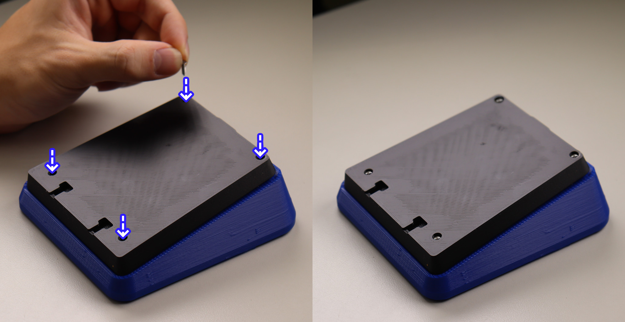
Step 10: Screw the Base into the Top
💡
Tip: You are safe to flip the frame upside down for this and future steps.
- Slowly drive the screws into the four holes in the top until you feel resistance.
🚨
Warning: Only screw until the frame feels firmly together. If you use too much force, you may break the frame.
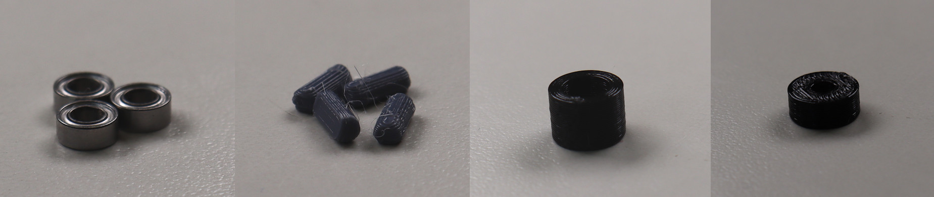
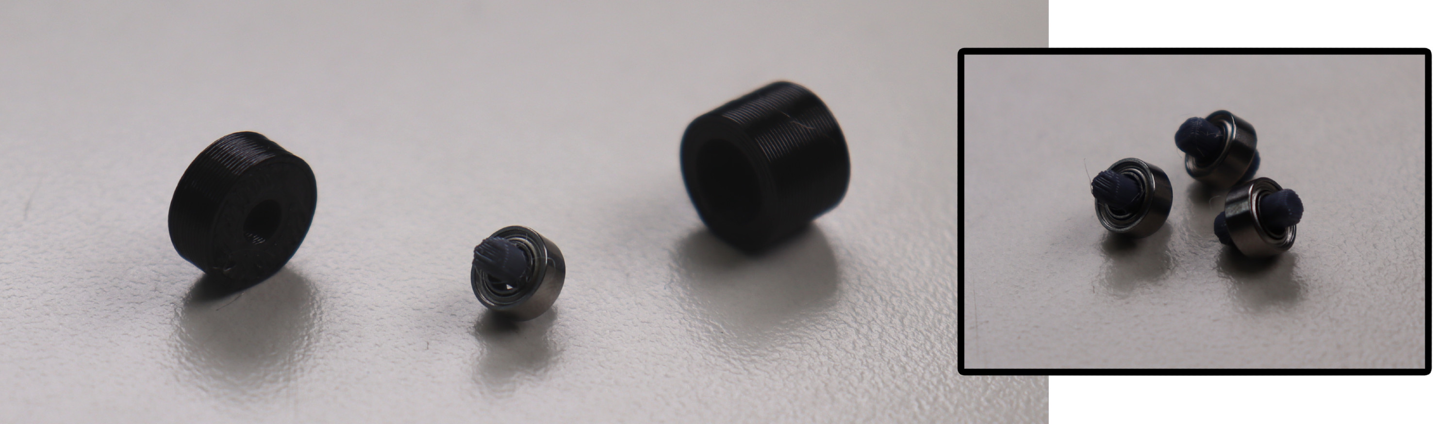
Step 11: Prepare Roller Bearing Parts
- 3x Roller Bearing
- 3x Roller Bearing Dowel
- Bearing Press Jig (Taller Half + Shorter Half)
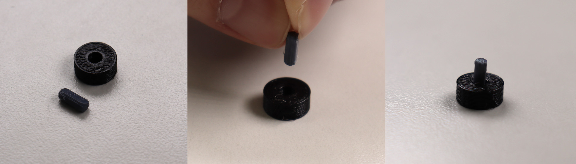
Step 12: Insert Roller Bearing and Bearing Dowel into Bearing Press Jig
- Insert the bearing into the taller half of the bearing press jig.
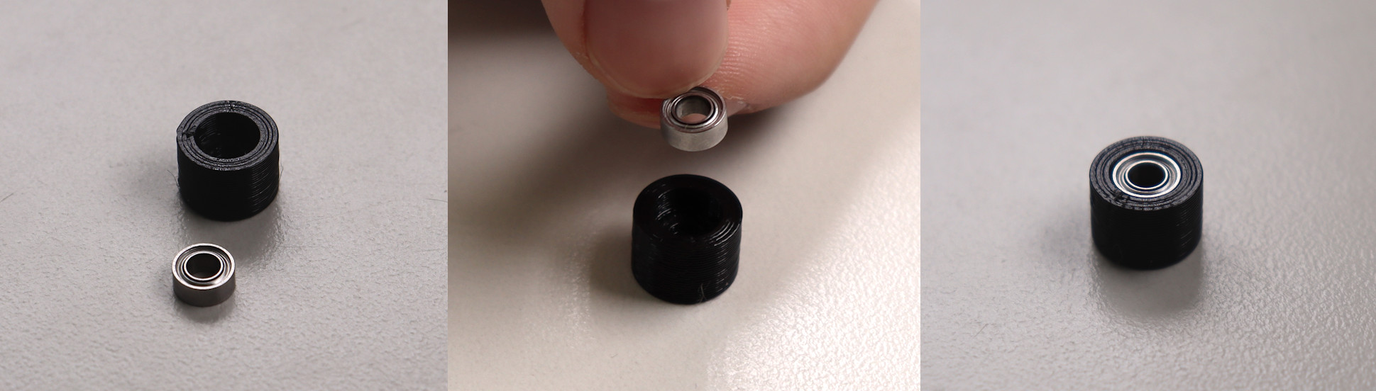
- Insert dowel into the shorter half of the bearing press jig.
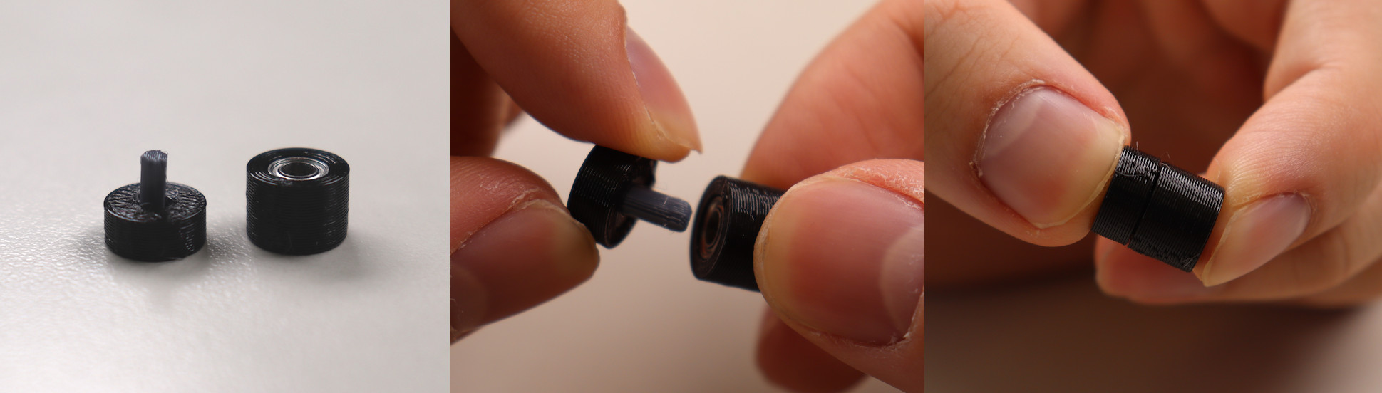
Step 13: Press the Bearing Jig Together
- Press the bearing press jig together.
🚨
Warning: This may require a surprising amount of force; try your best not to bend the roller bearing dowel. If you do, there are spares included in the assembly kit.
Step 14: Remove roller bearing from bearing press jig and repeat
- Remove the the roller bearing from the press jig.
- Repeat 3 times to end with 3 roller bearings.
Step 15: Insert roller bearings into the Top Piece
- Insert the roller bearings into the 3 holes in the top of the frame.
- Ensure the bearings are pressed all the way into the case.
💡
Tip: Needle nose pliers or some similar tool can be used to ensure that the bearing is fully seated.
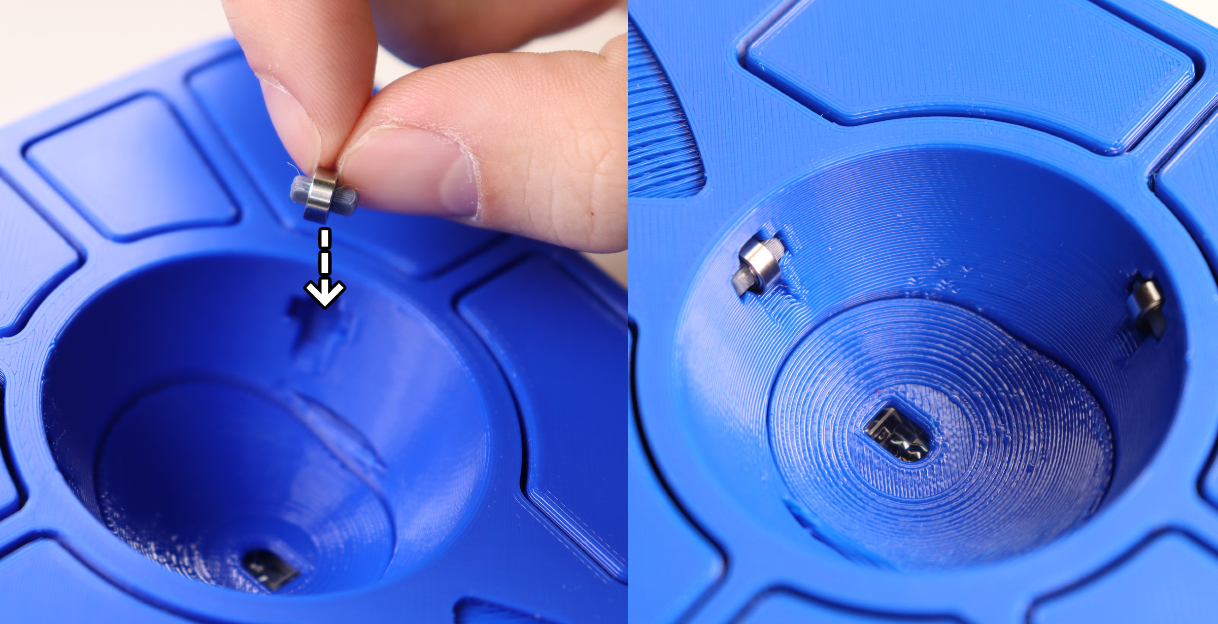
🚨
Warning: If the bearings aren't seated all the way, there's a good chance that the ball will become badly scratched.
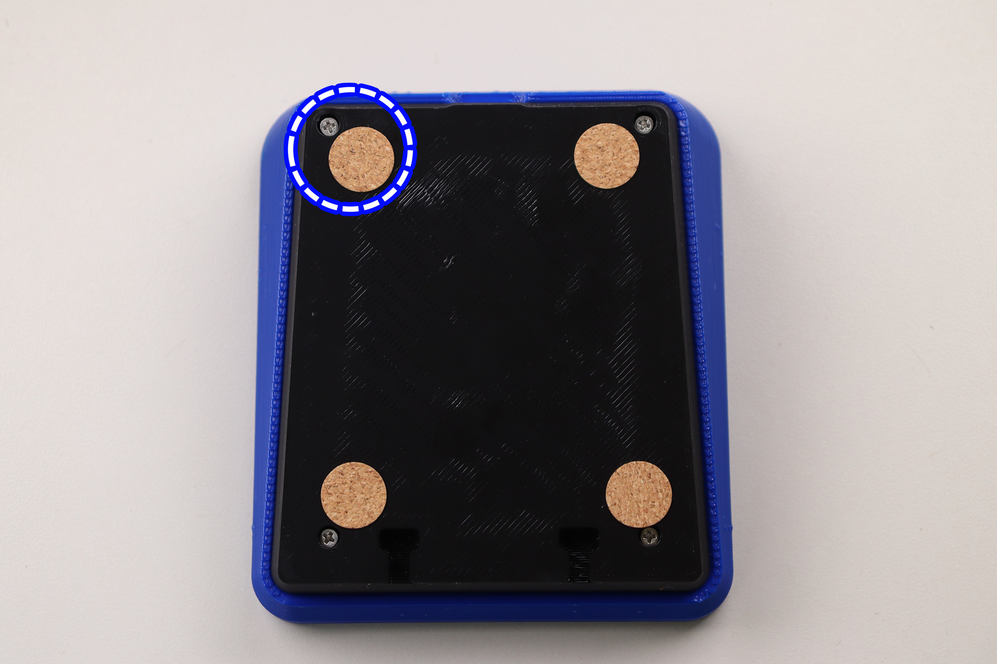
Step 16: Place Friction Pads on Base
- Flip the adept frame upside down.
- Place the friction pads on each corner of the frame.
💡
Tip: Do your best not to cover the screw holes with the friction pads, as this will make opening the case more difficult in the future.
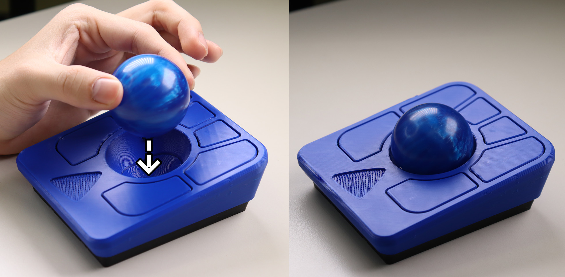
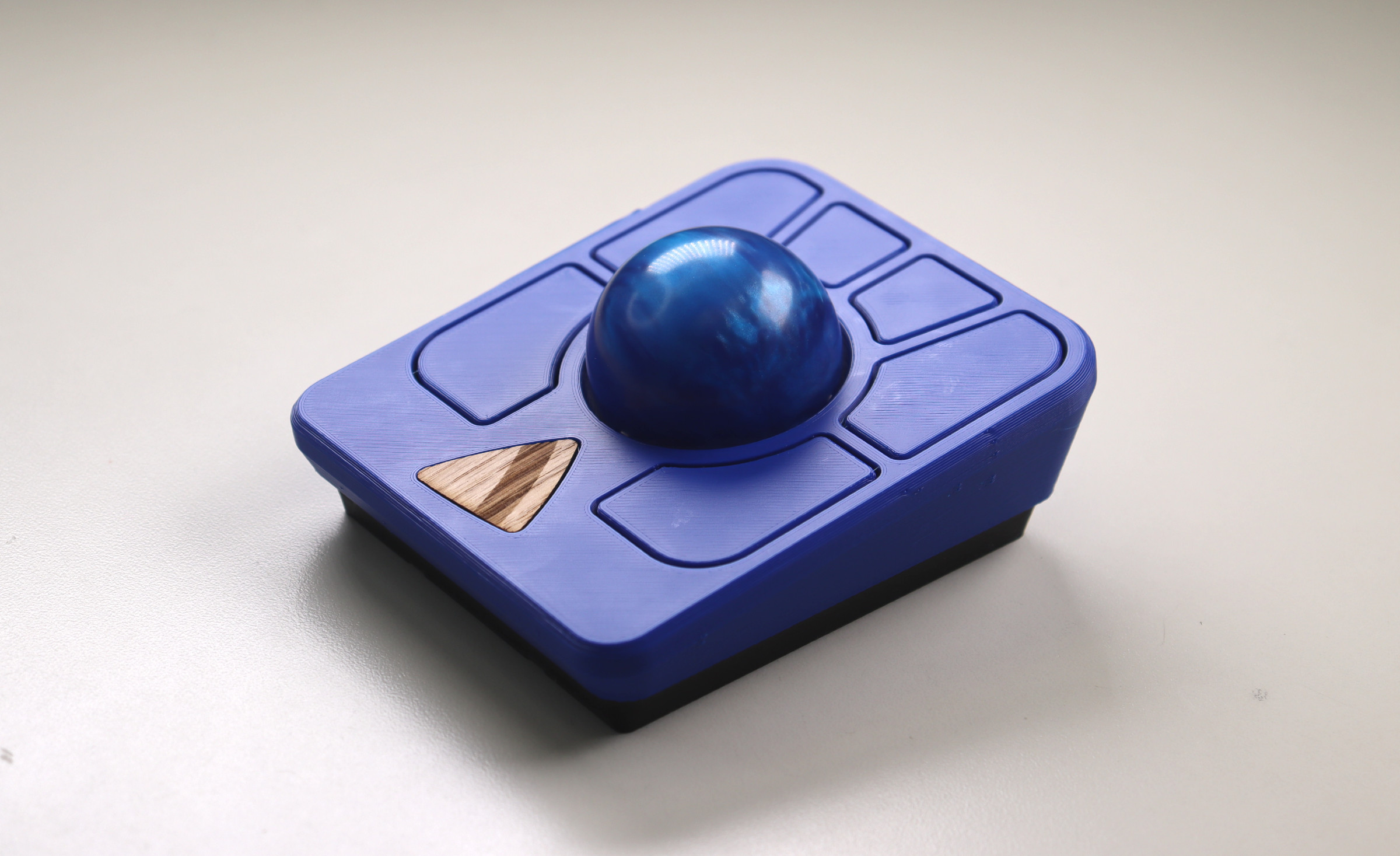
Step 17: Insert the ball
- Insert the track ball into the hole in the middle of the adept frame.
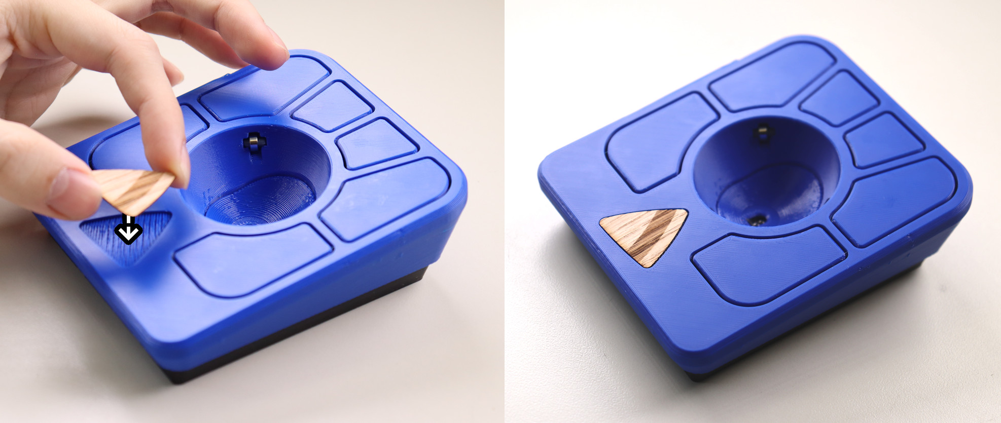
Step 18: Peel and stick the logo to the Top
- Insert the logo in the indent on the top of the frame.
Step 19: All done!
Post Steps:
Spin the ball to break in the bearings
- Spin the ball around for around 3 minutes to break them initially before any use
- The bearings may take around a week to become fully broken-in/smooth
Verify the Ploopy Adept Trackball is working correctly
- Plug the adept trackball mouse into the computer using a USB-C cable
- Move the ball around, it should move the cursor
Check out Post Build FAQ
- Post Build FAQ
- Contains various information about things you can do after initial assembly!
ℹ️
Info: If the trackball is not working, consult our
troubleshooting guide
for further steps.