Assembly instructions
Step 1: Prepare necessary tools
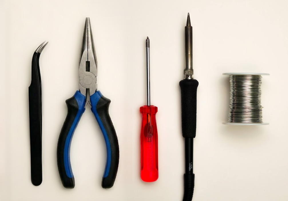
- A #1 Phillips head screwdriver
- Soldering iron
- Solder
- Optional: tweezers
- Needle-nose pliers
💡
Tip: A similar smallish Phillips head screwdriver could work.
Step 2: Prepare parts for PCB soldering
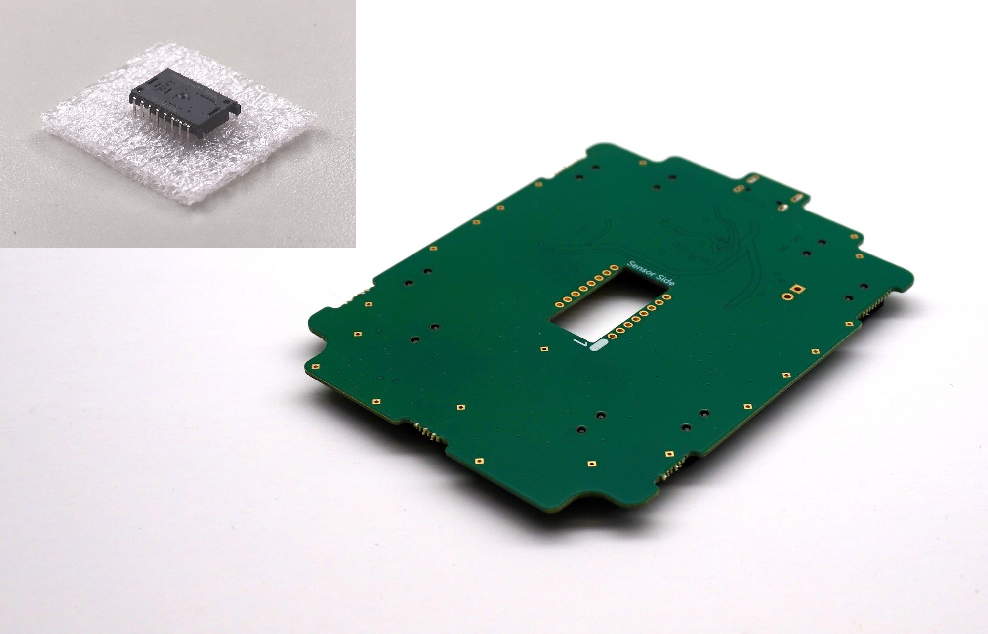
Prepare the following components as pictured below:
- Printed circuit board
- PMW-3360 chip
💡
Tip: The PMW-3360 chip will come in a small piece of foam. Go ahead and remove it now.
Step 3: Solder PMW-3360 sensor to printed circuit board
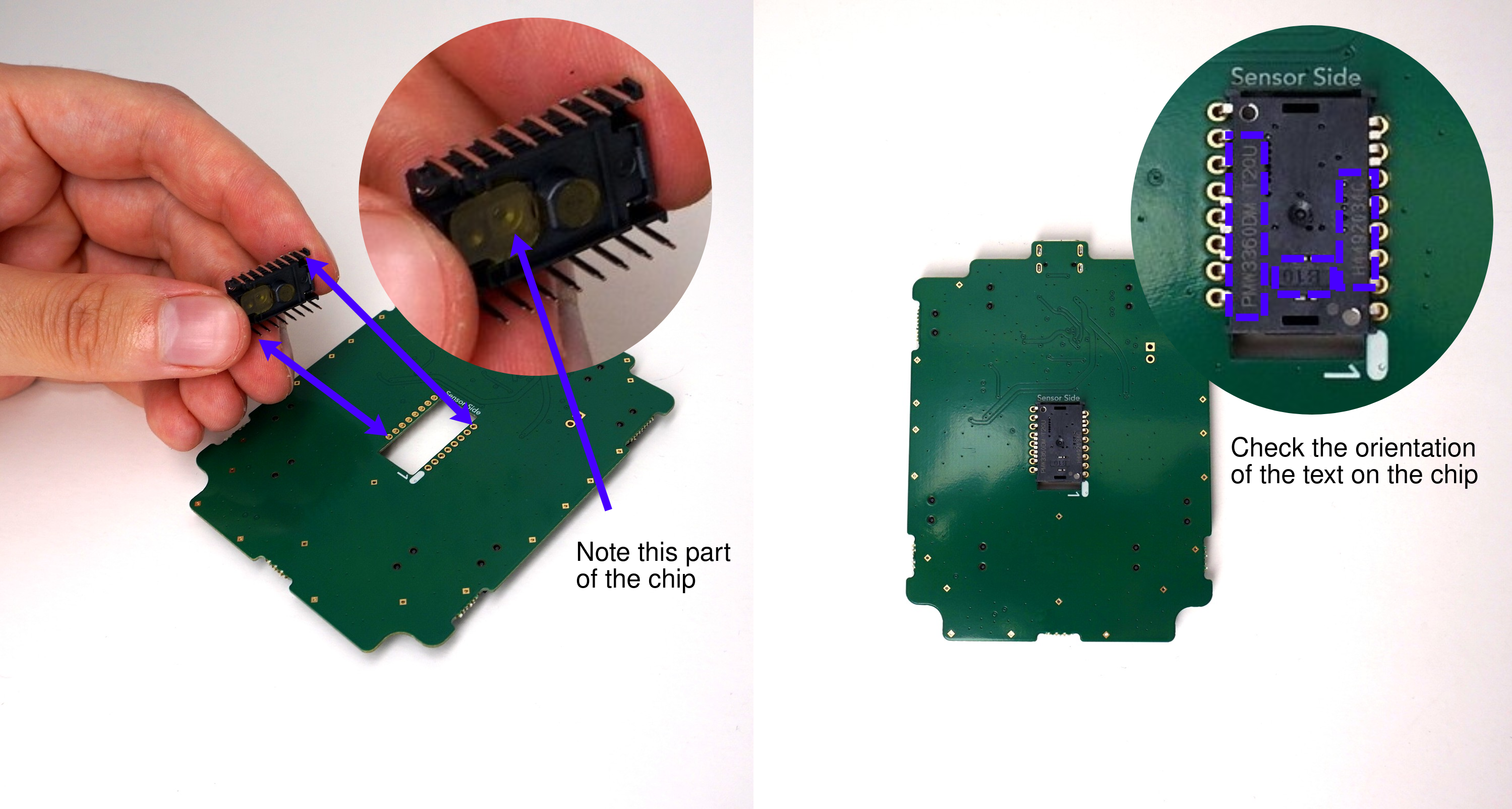
- Place the sensor onto the circuit board, ensuring the orientation is correct.
🚨
Warning: Use the cues presented in the following images to ensure the sensor is oriented correctly.
🚨
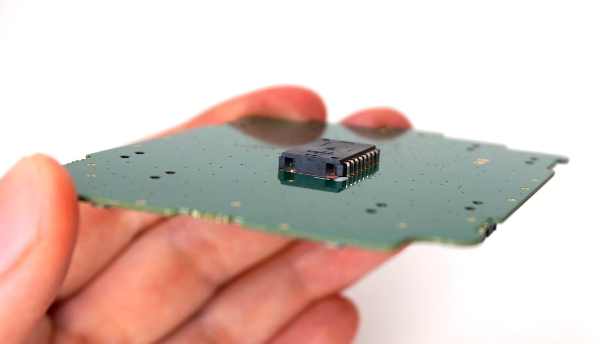
Warning: The sensor must be flat down as far as it can possibly slide into the holes before soldering.
Step 4: Remove the tab of kapton tape on the PMW-3360 chip
💡
Tip: Try to do this step in a dust-free environment.
- There are two small tabs of orange tape covering the sensor's main holes. Remove them now.
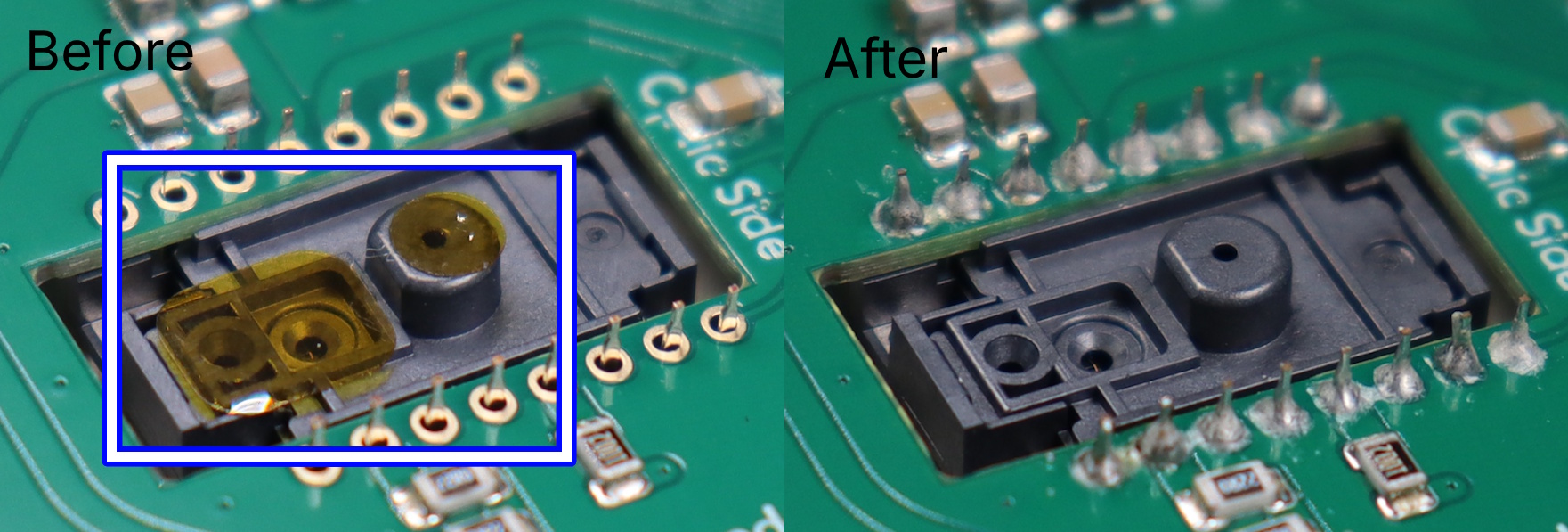
ℹ️
Info: Check your solder joints during this step to ensure that they are good. To know if they are good, consult the
soldering FAQ.
Step 5: Attach the PMW-3360 optic to the PMW-3360 chip
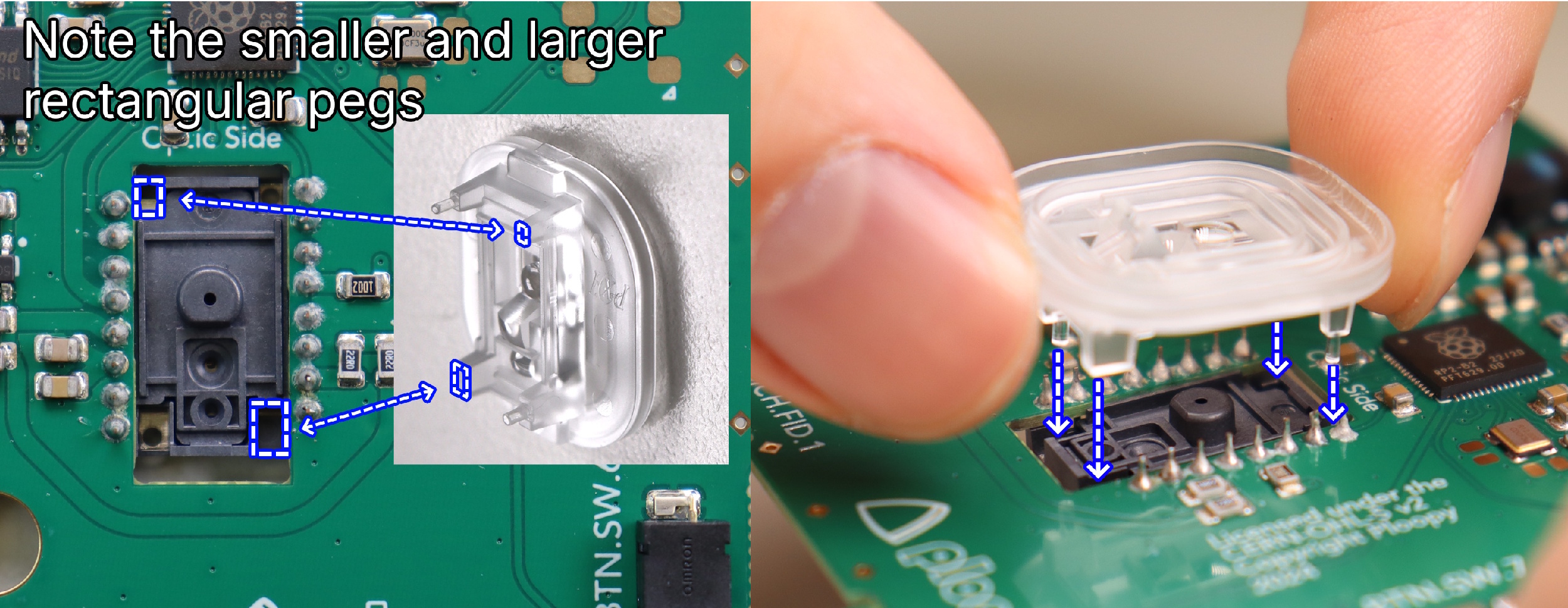
- Orient the optic as shown in the image before insertion.
🚨
Warning: It should NOT require any force to insert fully; if it does, remove it and check the orientation before trying again.
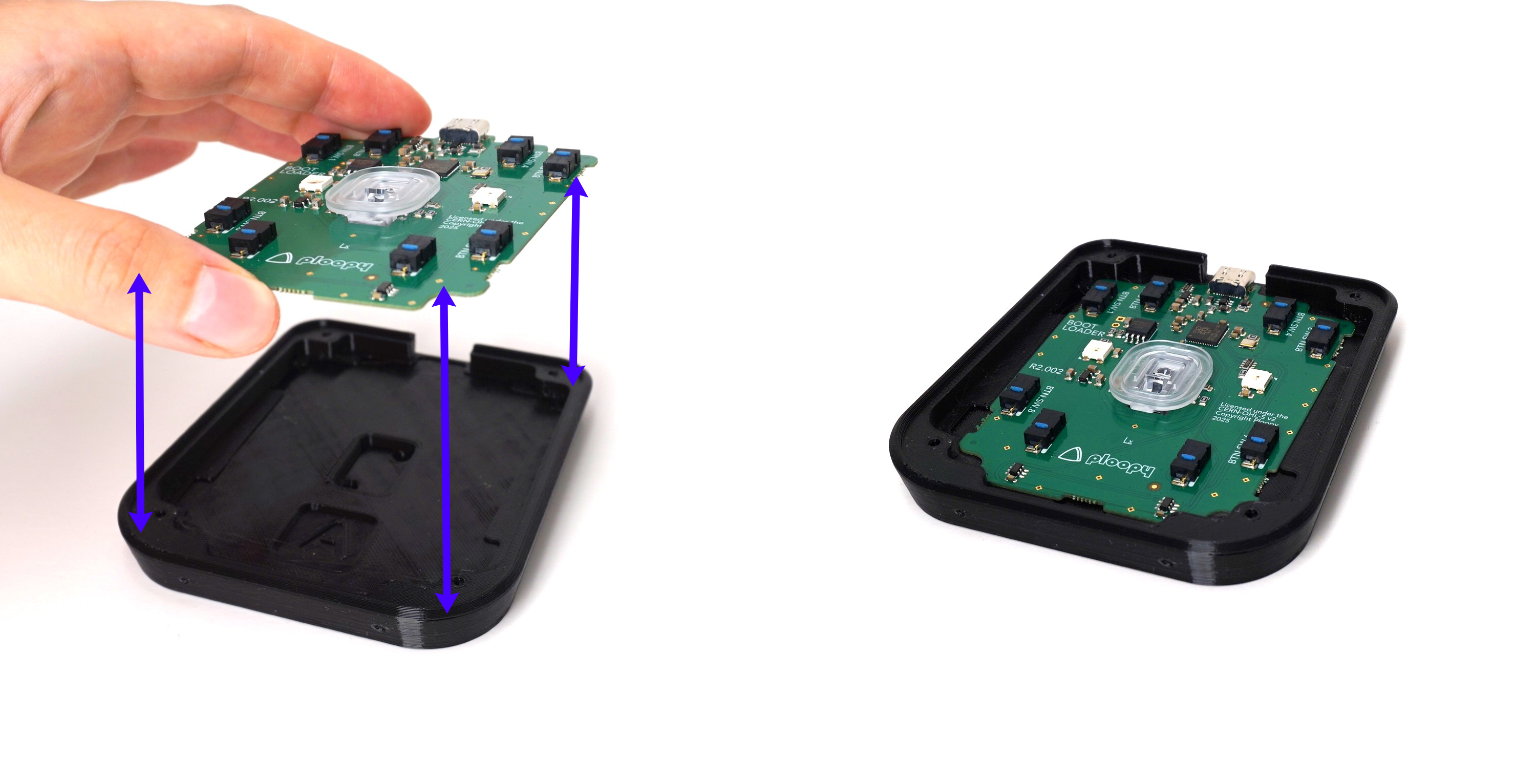
Step 6: Place the PCB into the Base
- The PCB should not require force to insert into the Base.
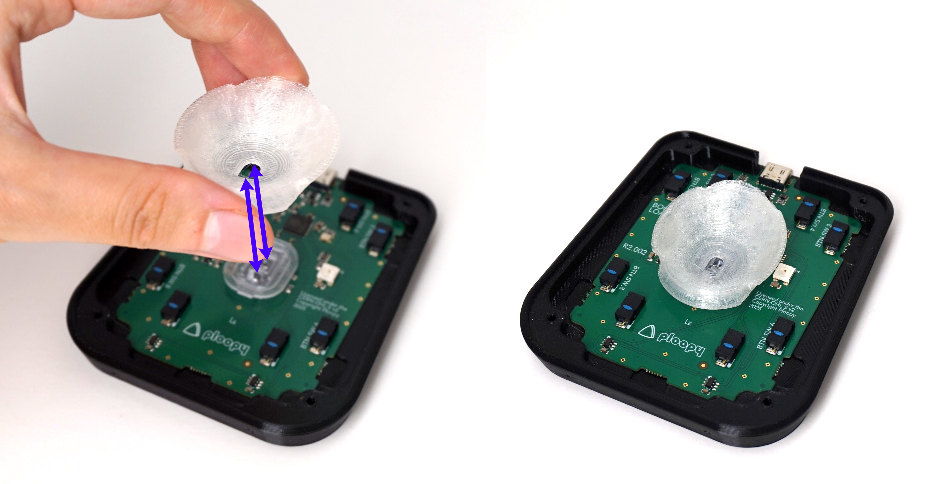
Step 7: Place the Sensor Cap on the PCB
- Place the Sensor Cap on the PCB as shown in the image.
💡
Tip: The Sensor Cap doesn't snap onto the PMW-3360 optic. It "floats" on top of the optic for now. Once fully assembled, the Sensor Cap will be securely held down.
Step 8: Insert one magnet into one Knob
💡
Tip: The orientation of the first magnet does not matter. Insert the magnet into either hole, in any direction it will fit.

Step 9: Align second magnet correctly
🚨
Warning: If the magnet is not aligned correctly, the Knob will not function, and the magnets are very difficult to remove!
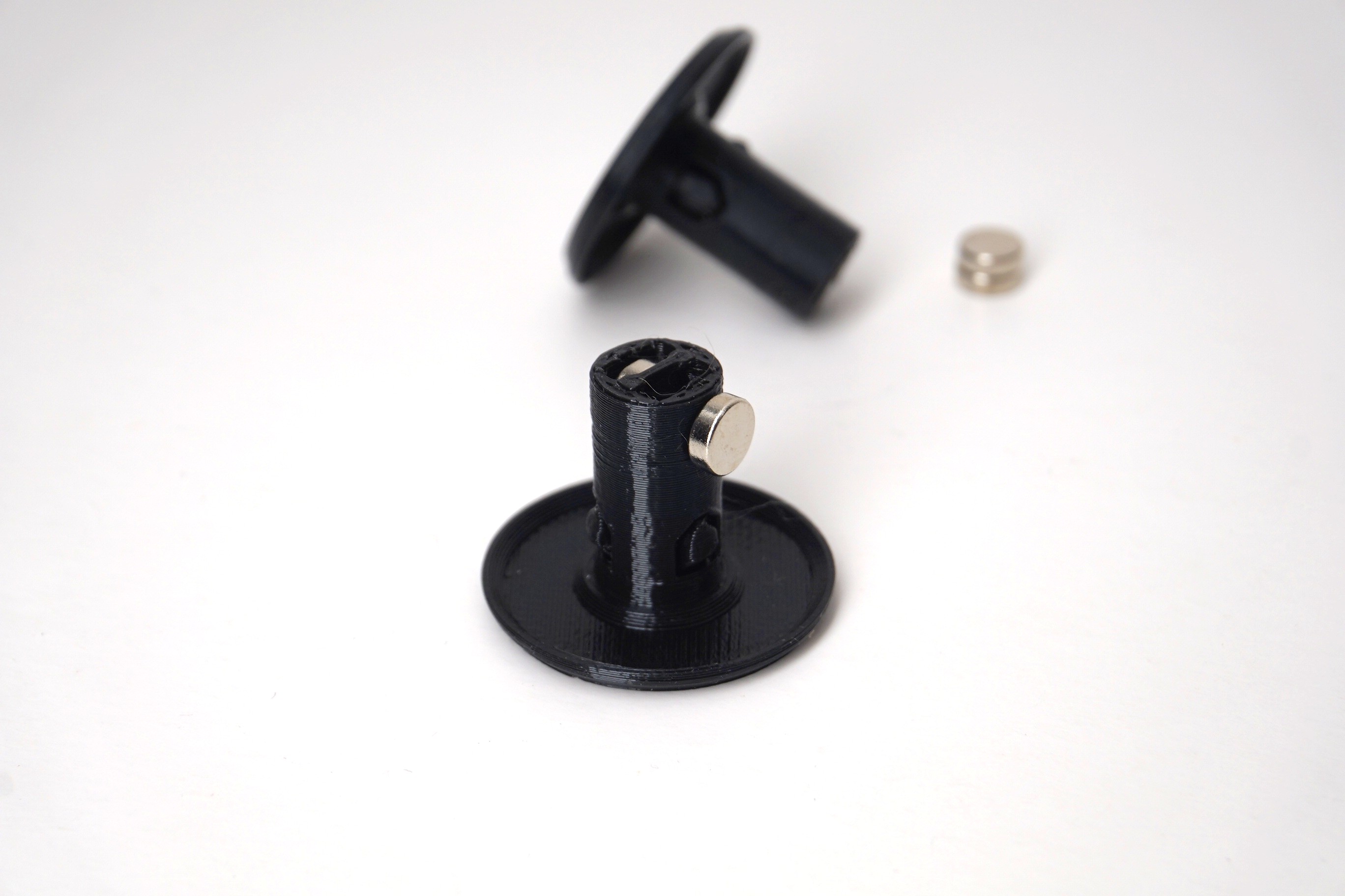
Step 10: Insert second magnet
💡
Tip: If the second magnet is oriented correctly, the first magnet will try to pull it into the hole. If the magnet is not oriented correctly, the first magnet will try to repel it out of the hole.
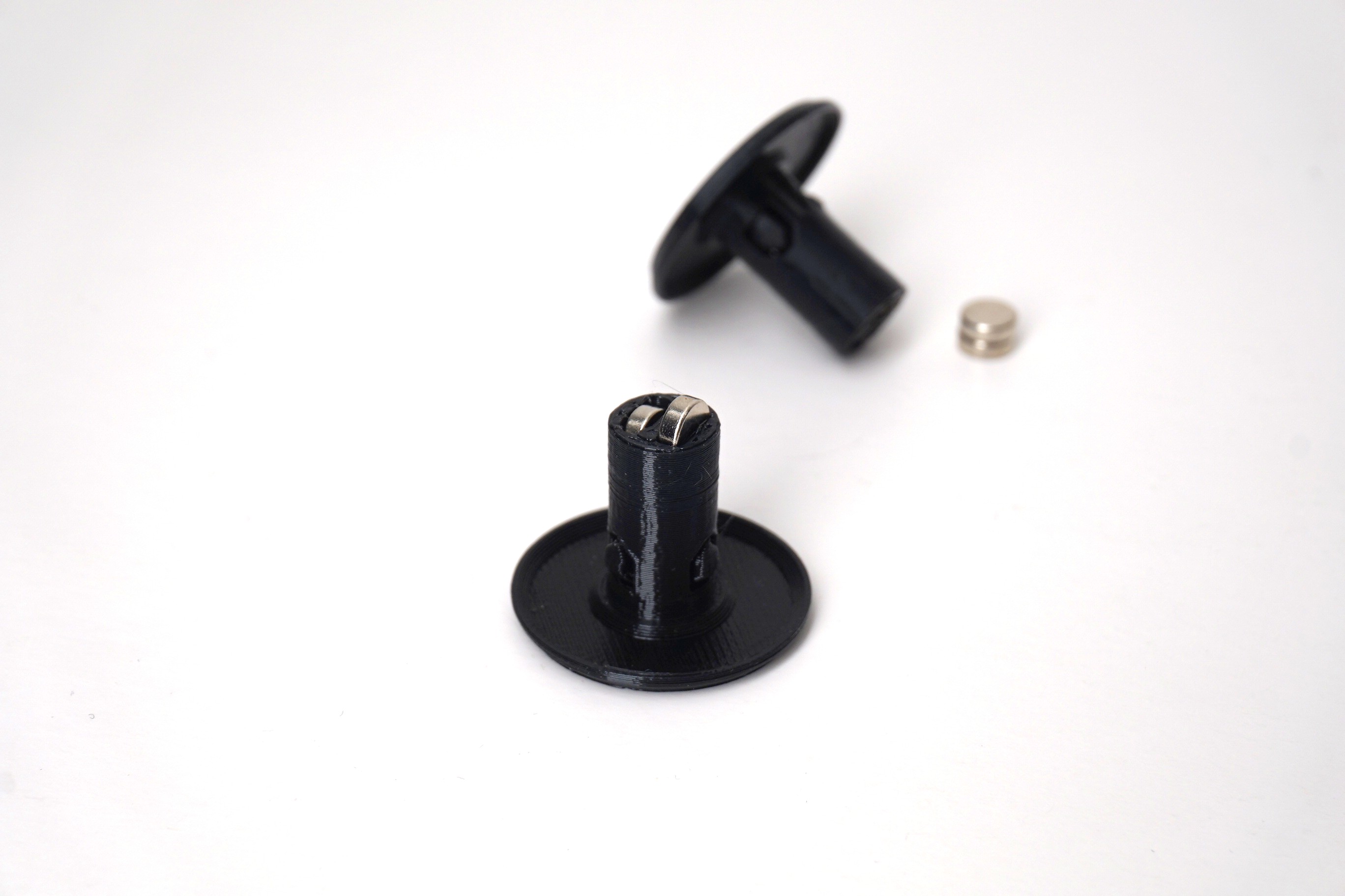
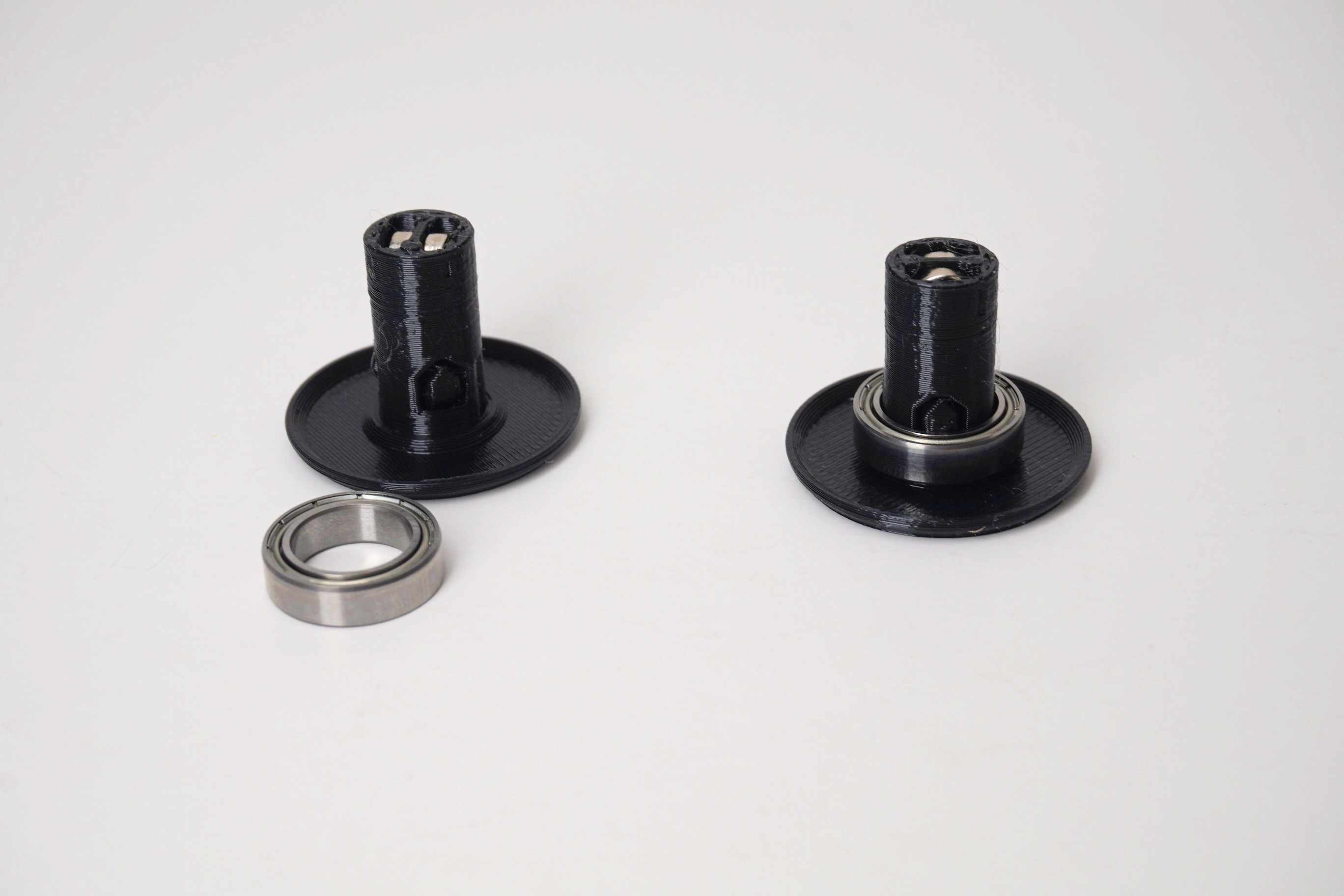
Step 11: Slip large bearing onto Knob shaft
💡
Tip: This may require some force.
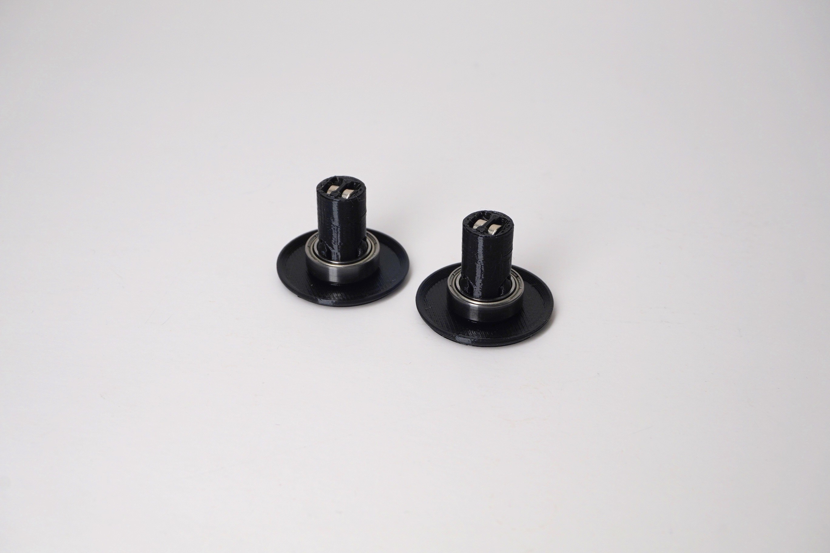
Step 12: Repeat Steps 8-11 for the second Knob
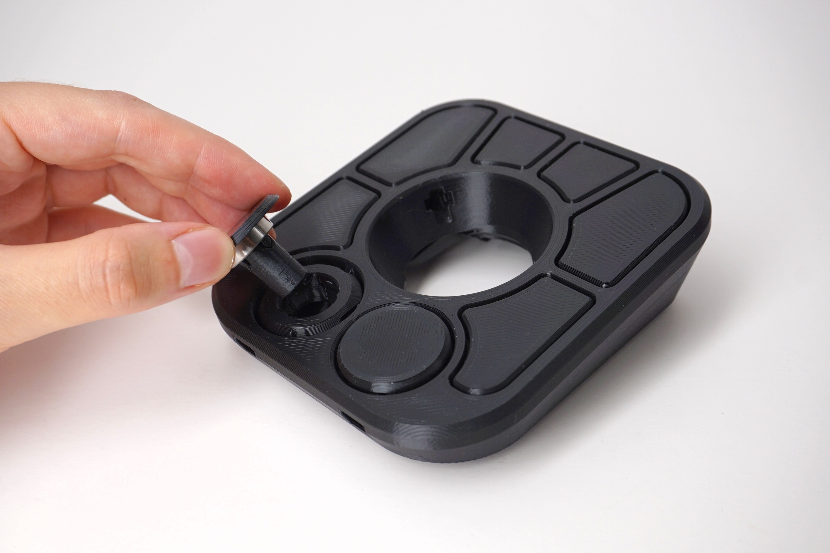
Step 13: Insert Knobs into Top
💡
Tip: This may require some force.
Step 14: Place the Top onto the Base
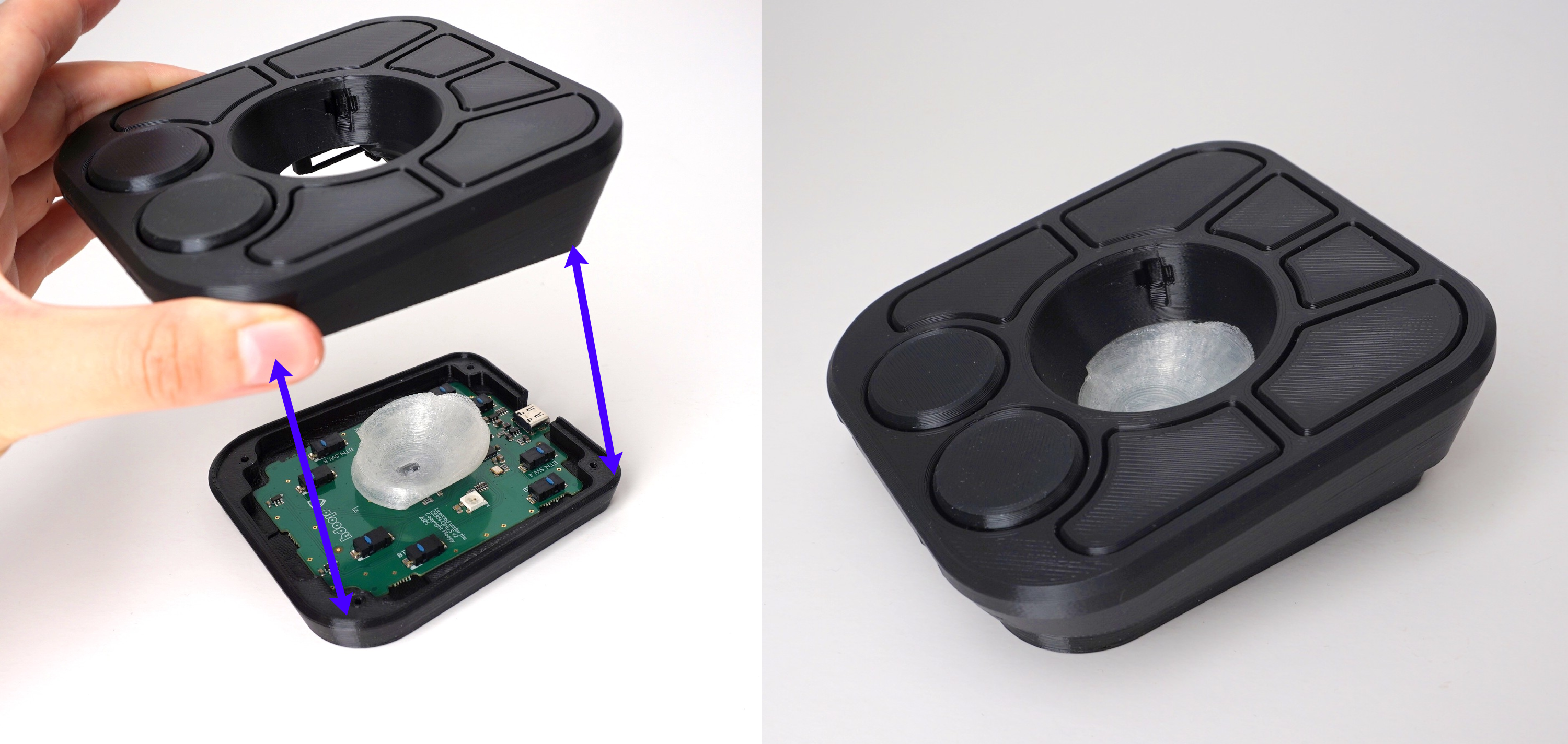
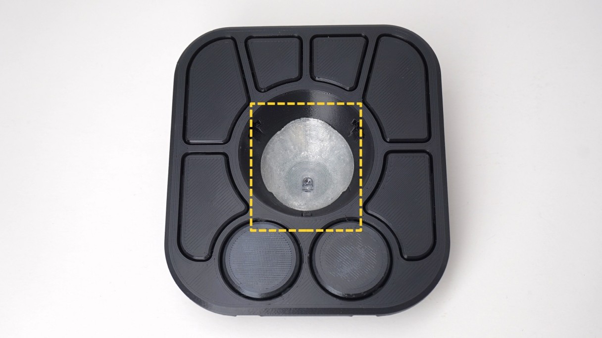
💡
Tip: If necessary, adjust the position of the Sensor Cap as you're lowering the Top onto the Base. It should end up looking like the image.
Step 15: Screw the Base into the Top
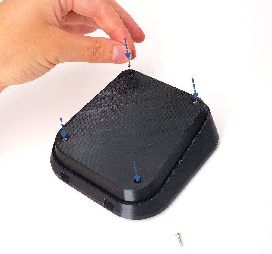
💡
Tip: Only screw until the frame feels firmly together. If you use too much force, you may break the frame.
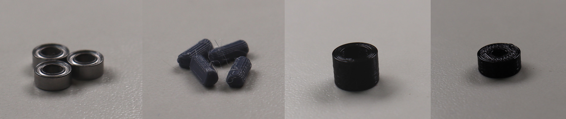
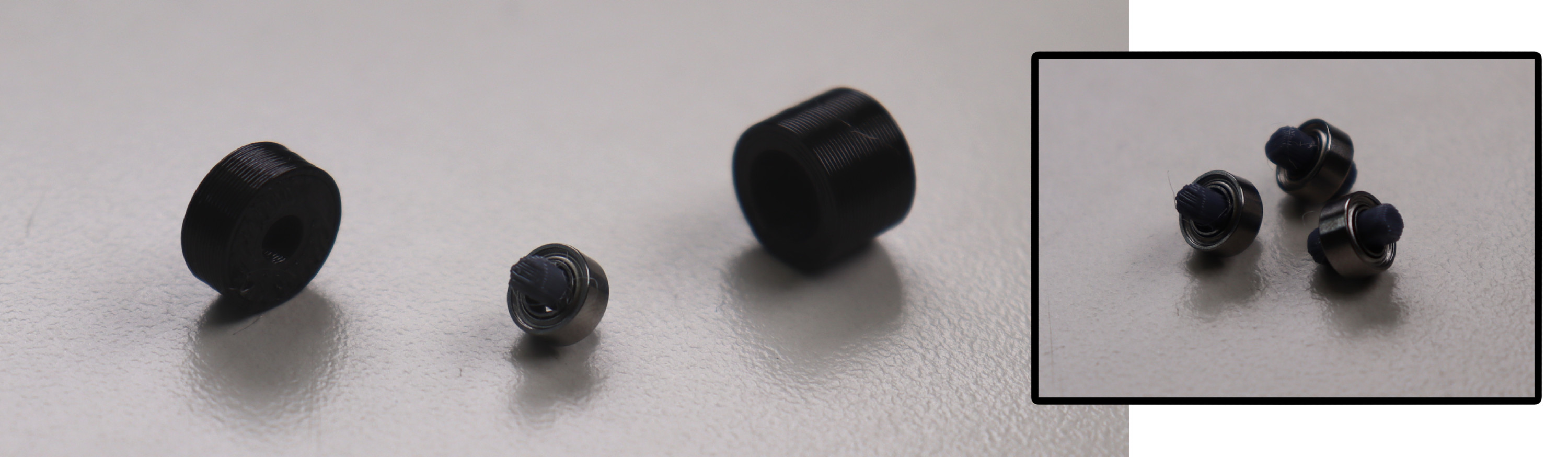
Step 16: Prepare Roller Bearing Parts
- 3x Roller Bearing
- 3x Roller Bearing Dowel
- Bearing Press Jig (Taller Half + Shorter Half)
Step 17: Insert Roller Bearing and Bearing Dowel into Bearing Press Jig
- Insert the bearing into the taller half of the bearing press jig.
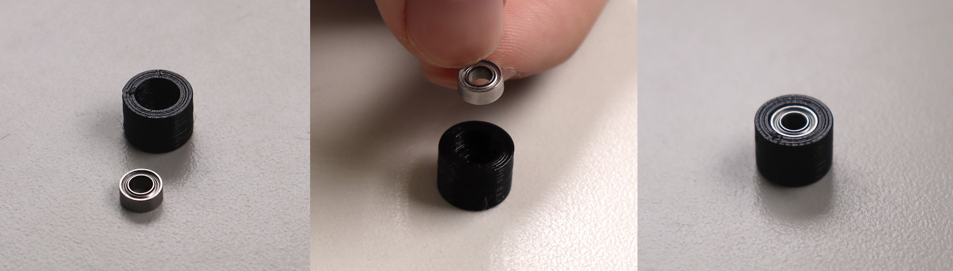
- Insert dowel into the shorter half of the bearing press jig.
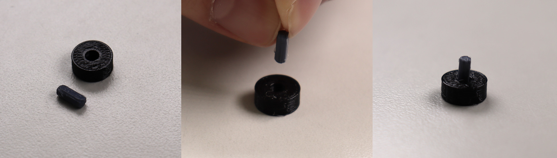
Step 18: Press the Bearing Jig Together
💡
Tip: This may require a surprising amount of force; try your best not to bend the roller bearing dowel. If you do, there are spares included in the kit.
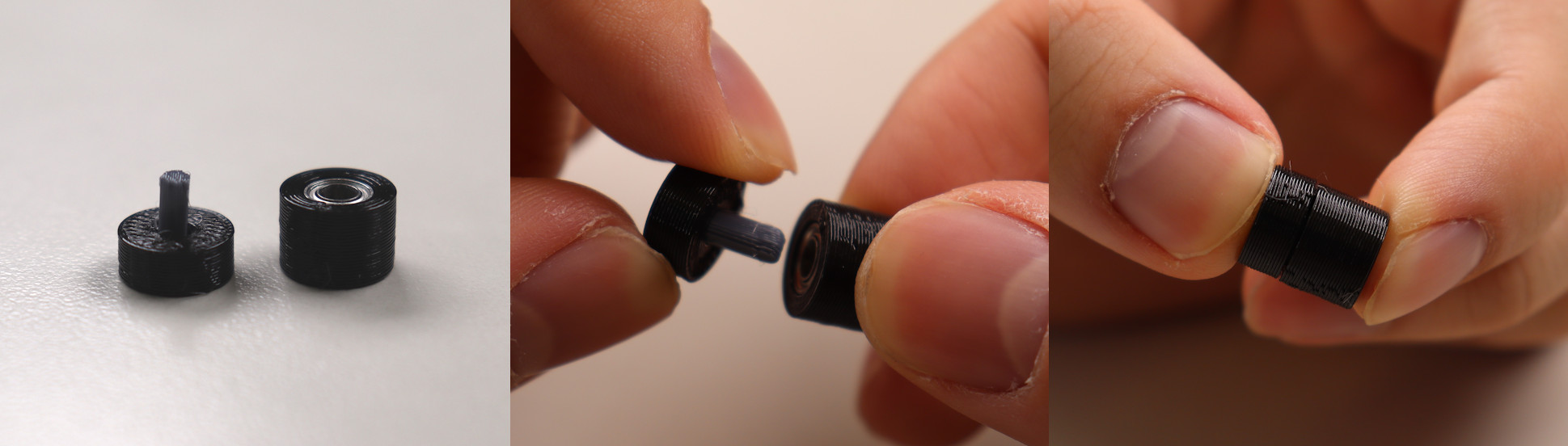
Step 19: Remove roller bearing from bearing press jig and repeat
- Remove the the roller bearing from the press jig.
- Repeat 3 times to end with 3 roller bearings.
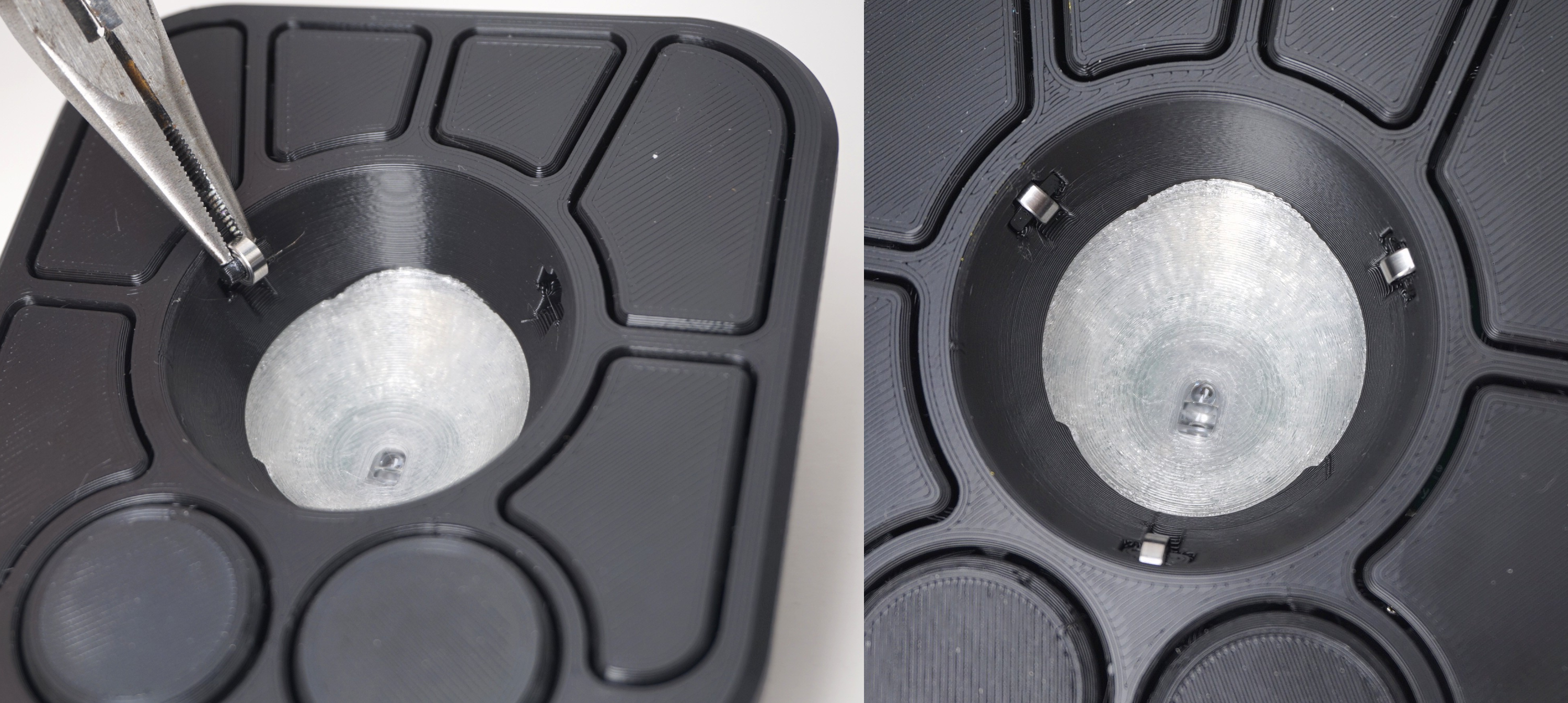
Step 20: Insert roller bearings into the Top
- Insert the roller bearings into the 3 holes in the top of the frame.
- Ensure the bearings are pressed all the way into the case.
💡
Tip: Needle nose pliers or some similar tool can be used to ensure that the bearing is fully seated.
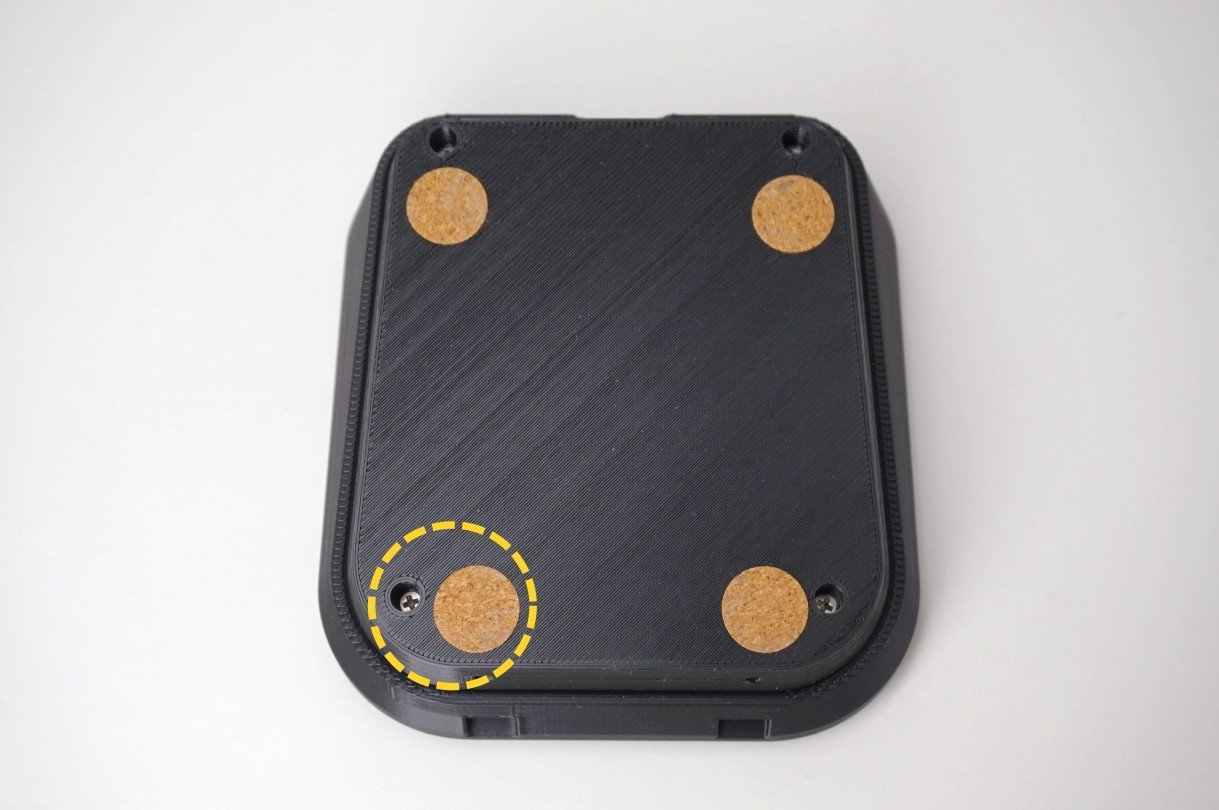
Step 21: Place Friction Pads on Base
- Flip the adept frame upside down.
- Place the friction pads on each corner of the frame.
💡
Tip: Do not cover the screw holes with the friction pads, as this will make opening the case more difficult in the future.
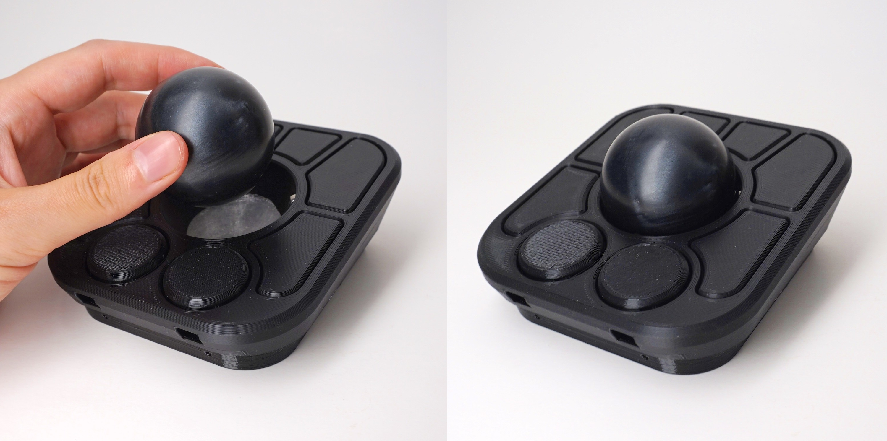
Step 22: Insert the ball
Step 23 (OPTIONAL): Screw the Wedge to the Top
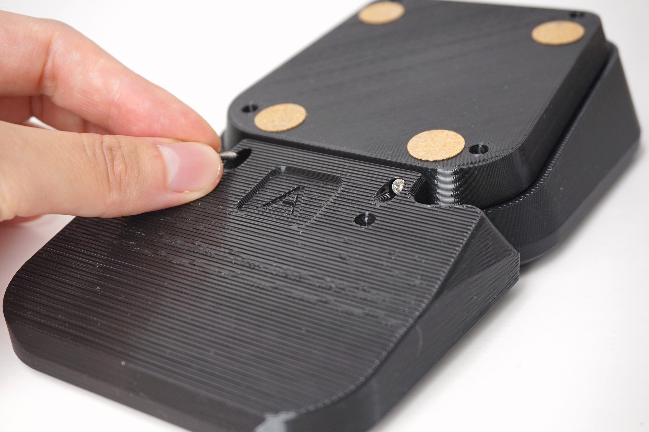
Step 24: All done!
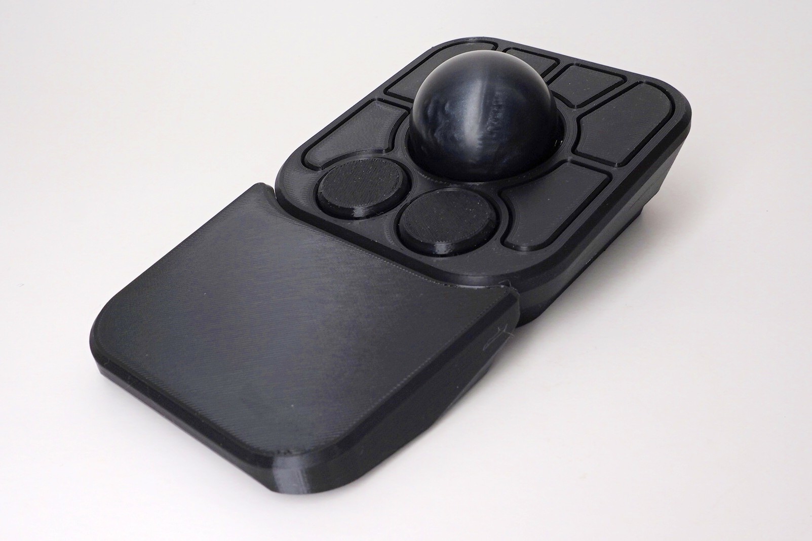
Post Build Steps:
Spin the ball to break in the bearings
- Spin the ball around for around 3 minutes to break them initially before any use
- The bearings may take around a week to become fully broken-in/smooth
Verify the device is working correctly
- Plug the A+ into a computer using a USB-C cable
- Move the ball around, it should move the cursor
ℹ️
Info: The default keymap for the A+ is here.
Check out Post Build FAQ
- Post Build FAQ
- Contains various information about things you can do after initial assembly!
ℹ️
Info: If the device is not working, consult our troubleshooting guide for further steps.